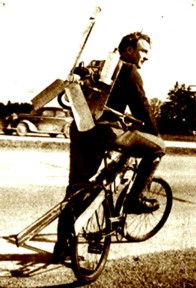
From the Monster GarageMotivationI have to cycle 20 miles to and from my house in the countryside every day to reach the university. I was going to buy a BMW but then I decided I would be more fun to modify my bicycle. Not content with the conventional approach to motorising a bicycle, which would be to drive the wheels via a chain or friction drive. I decided to use a air power to push the bicycle along. Leaving aside the obvious danger of large propeller, it has advantages from the design point of view, in that the engine can easily be removed and it is far more simple to engineer. Although the internet is packed with people that have converted bicycles to use various methods of propollsion such as old trainers insteed of wheels, Nitrous Oxide hybrid rockets and jet engines there are almost no propeller powered bicycles except what looks to be a very old fashioned device shown in the picture below.
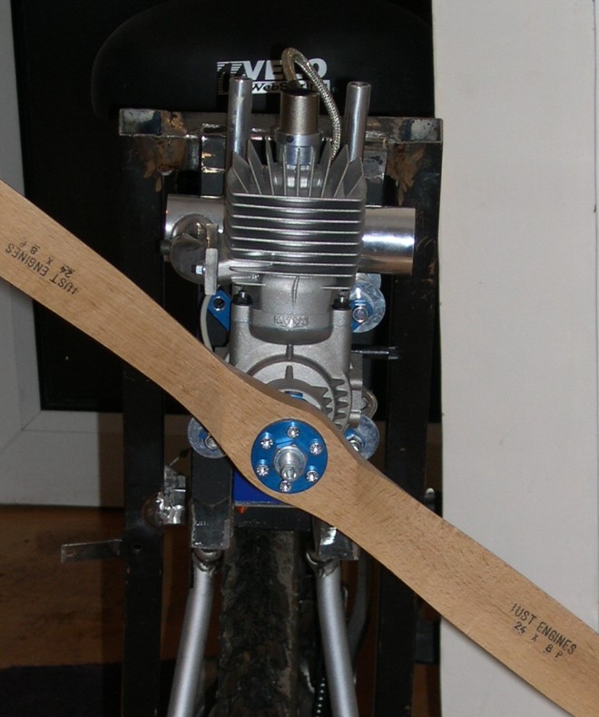
The bicycle I am using, is my "hard tail" Muddy Fox aluminium team-edition. It is very light and has convenient holes for mounting the frame to which the engine will be fixed. The EngineMy brother-in-law and I had experimented with a small strimmer engine driving a propeller the year before. With just 1 bhp, it just worked but only pushing the bicycle and rider at 3 mph it wasn't a viable for everyday use. Surfing the Internet, I found a very powerful large-scale radio control aircraft engine which I bought from Just Engines. The MVVS 3.6 is a 58 cc two-stroke engine, rated at nearly 8 hp but it is extremely light weighing just over 2 kg including the silencer it seems ideal for this application. It has a computer controlled electronic ignition and can drive a 26" propeller at 7500 rpm.
Air Bike PhysicsThe bicycle is pushed forward by the reaction force to the mass of air being forced through the propeller. (Newton's third law). The bicycle will accelerate according to Newton's second law F=ma where F is the force produced by the propeller and m is the mass of bicycle and rider. The force produced by the propeller is a complicated mix of the power of the engine and the design of the propeller. However, some insight can be obtained by using a much simple momentum theory. In the diagram below, the engine turns the propeller and does work on the airflow so there is an abrupt change in pressure across the propeller disk. The propeller acts like a rotating wing. A crossection through the blades would reveal that it is an aerofoil, and in the same way that a wing produces a change a lower pressure over its top surface, the rotating propeller blade sets up a lower pressure just behind the blade than in the free stream of air in front of the propeller. Downstream of the disk, the pressure eventually returns to free stream conditions, but at the exit, the velocity of the air is greater because the propeller does work on the airflow.
Since we would like to get the maximum thrust from the propeller using the least powerful engine, the propeller must be as efficient as possible. Well designed propellers are up to 90% percent efficient. A small amount of energy is lost through swirl, (rotation of stream tube) vibration and noise of the propeller. The efficiency of a propeller is defined as the ratio of available power to the engine power. This definition has the velocity as a factor which means that the efficiency approaches zero as the 'flight speed' goes to zero
The graph below shows plots the efficiency of a propeller against velocity for a fixed ratio of the engine power to the square of the propeller disk diameter. For low values of P/D2 , which would imply a low-power or large diameter propeller, the efficiency increases rapidly with the flight speed. This leads us to conclude, that it is a good idea to choose the largest size of propeller for a given engine power, since although the rotational speed may be lower, the mass of air accelerated will be greater. Hence the reason for large, slowly turning propellers on solar aircraft or human-powered, flying vehicles. For large values of P/D2 the efficency of the propeller increases slowly. The dashed line is efficiency curve for my engine and propeller size the efficency will be quite low. However, this curve is for the engine running at full power. If the engine speed is reduced, then P/D2 would also reduce and the efficiency would increase at low flight speed.
If we plot the thrust generated, given the engine's power and the efficiency of the propeller we can see how the thrust drops with increasing speed. Initially the thrust starts at nearly 260 N (approx 26 kg) at full power. As we can see the rate at which the thrust decreases for low speeds is greater than at high speeds which is a direct result of the increasing efficiency at higher speeds. I am not suggesting however, that the bicycle would reach 100 m/s! However for model aircraft such high speeds are possible.
Of course, in the real world there are other forces to contend with namely, rolling friction and drag. The frictional forces are due to the bearings and tyres. If the tyres are pumped up hard then the area in contact with the road is small and the frictional forces will be small enough to be neglected. Air resistance or drag is a different matter. The force scales with the velocity squared and in the end is the limiting factor in determining how fast the bicycle will travel once the engine's power and propeller size and pitch are decided upon. The drag is given by
Cd is the drag coefficient. This is dificult to determine theoretically and is usually found by using a wind tunnel. Estimates range from 0.88 for a racing bicycle to 1.1. I choose a conservative 1.1 and the cycle frontal area as 5.5 ft2 (0.61 m2). We can write this as a non-linear differential equation.
With the solution For the force produced by the propeller I have taken a value of 35 lbs (175 N) which is what was quoted by the model shop. We can plot this solution over time, using ρ =1.25 kg/m-3, mbike= 70 kg (I am very light) and the values of the other parameters above we get a plot of velocity against time.
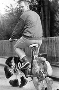
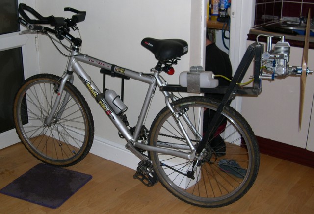
If this is correct then the top speed will be 46 mph. Torque and Gyoscopic Effects One of the unwanted effects of using a propeller to power a bicycle are the torque acting on the bicycle and the angular momentum of the propeller. The rotating propeller causes a reaction force which acts in the opposite direction to the propeller. In addition the conservation of angular momentum will produce forces to counteract the change in direction of the spinning propeller. The effect can be demonstrated if you hold a spining bicycle wheel out in front of you and try to turn keeping the bicycle wheel steady. Build TimeMy first idea was to make a backpack which I would wear, like a motorised paraglider engine. However given the large size of the propeller, power of the engine and limitation of the tools and equipment available to me. This is was decided against on the grounds of being too dangerous. The first part was design the frame which would support the engine. I libberated the necessary box steel section tubing from an old desk which was being thrown out. This was then welded together to make a framework which could be easily bolted onto the bicycle without any major modification to the bicycle. A 1.6 litre fuel tank was mounted onto the framework and the engine bolted to the frame. The framework needs to put the engine far enough back to avoid the spinning prop when getting on the bicycle. The picture below shows the bicycle with the engine fitted. No propeller guard yet, although this is quite essential as the ends of the blades will be travelling at more than 100 mph when running.
TestingThe engine is new and therefore has to be run-in to make it reliable. A mixture of petrol and synthetic racing oil is used in the ratio of 40:1. |